Page: 1
/ 14
Total 65 questions
Juniper JN0-281 Data Center, Associate Exam Practice Test
Question 1
Which two statements about IBGP are correct? (Choose two.)
Answer : C, D
IBGP (Internal Border Gateway Protocol) is used to exchange routing information between routers within the same AS (Autonomous System).
Step-by-Step Breakdown:
TTL of 255:
By default, IBGP sessions are established with a TTL (Time to Live) value of 255. This allows IBGP neighbors to communicate over multiple hops within the AS without requiring any additional configuration.
Full Mesh Requirement:
IBGP requires a logical full mesh between all IBGP routers to ensure that routing information is fully distributed within the AS. Since IBGP does not propagate routes learned from one IBGP peer to another by default, a full mesh topology is needed unless route reflectors or BGP confederations are used.
Juniper Reference:
IBGP Full Mesh: Juniper recommends using route reflectors in large networks to simplify IBGP full-mesh requirements.
Question 2
What is the definition of a trunk interface on a switch?
Answer : A
A trunk interface on a switch is used to carry traffic for multiple VLANs between switches or between a switch and another network device, like a router. Trunk interfaces use 802.1Q tagging to identify which VLAN the traffic belongs to.
Step-by-Step Breakdown:
Trunk Ports:
Trunk ports are typically used for inter-switch links or switch-to-router links where multiple VLANs need to be carried over the same physical connection.
VLAN traffic is tagged with a VLAN ID to ensure that it is properly identified as it crosses the trunk link.
802.1Q VLAN Tagging:
Trunk ports use 802.1Q to tag Ethernet frames with the VLAN ID. This ensures that frames are correctly forwarded to the appropriate VLANs on the other side of the trunk.
Juniper Reference:
Trunk Interface Configuration: In Juniper switches, trunk ports are configured to carry tagged traffic for multiple VLANs, which is essential for interconnecting multiple network segments.
Question 3
Exhibit:
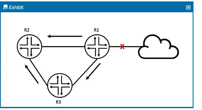
R2 received an OSPF update from R1, and it received the same update from R3.
Referring to the exhibit, what will R2 do?
Answer : C
In the exhibit, R2 receives the same OSPF update from both R1 and R3. OSPF has mechanisms to prevent unnecessary processing of duplicate LSAs (Link-State Advertisements).
Step-by-Step Breakdown:
OSPF LSA Processing:
OSPF uses LSAs to exchange link-state information between routers. When a router receives an LSA, it checks if it already has a copy of the LSA in its Link-State Database (LSDB).
Duplicate LSAs:
If R2 has already received and processed the update from R1, it will ignore the update from R3 because it already has the same LSA in its database. OSPF uses the concept of flooding, but it does not reprocess LSAs that it already knows about.
R2 Behavior:
R2 will keep the update from R1 (the first one it received) and will ignore the same LSA from R3, as it is already in the LSDB.
Juniper Reference:
OSPF LSA Processing: Junos adheres to OSPF standards, ensuring that duplicate LSAs are not processed multiple times to avoid unnecessary recalculations.
Question 4
Layer 2 interfaces operate in which two modes? (Choose two.)
Answer : A, C
Comprehensive Detailed Step by Step Explanation with all Juniper Data Center References
Layer 2 interfaces on a switch operate in two key modes: Access and Trunk.
Step-by-Step Breakdown:
Access Mode:
Access ports are used to connect end devices, like PCs or servers, and they are assigned to a single VLAN. These interfaces handle untagged traffic and do not pass VLAN tags.
Example: A port assigned to VLAN 10 will only handle traffic for that VLAN.
Trunk Mode:
Trunk ports are used to connect switches or other networking devices that need to handle traffic from multiple VLANs. Trunk interfaces carry tagged traffic, allowing multiple VLANs to traverse the same physical link.
Trunk ports typically use 802.1Q VLAN tagging to differentiate between VLANs.
Juniper Reference:
Access and Trunk Ports: Juniper switches use these modes to manage VLAN traffic at Layer 2, with access ports handling untagged traffic and trunk ports handling tagged traffic from multiple VLANs.
Question 5
Exhibit:
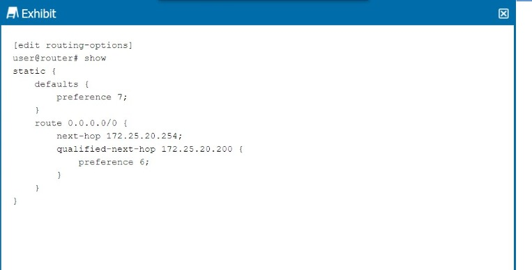
Referring to the exhibit, which next hop will be preferred in the routing table?
Answer : C
In the exhibit, we see a static route configuration with two possible next hops for the default route (0.0.0.0/0):
next-hop 172.25.20.254 with the default preference of 7.
qualified-next-hop 172.25.20.200 with a preference of 6.
Step-by-Step Breakdown:
Preference Value:
In Junos OS, the preference value is used to determine which route should be preferred in the routing table. The lower the preference value, the higher the priority for the route.
Comparison:
In this case:
The next hop 172.25.20.254 has a preference of 7.
The qualified-next-hop 172.25.20.200 has a preference of 6.
Preferred Next Hop:
Since 172.25.20.200 has a lower preference (6) compared to 172.25.20.254 (7), it will be the preferred next hop in the routing table, assuming both next hops are reachable.
Juniper Reference:
Qualified Next Hop: In Junos, static routes with multiple next-hop options are selected based on the preference value, with the lower value being preferred.
Question 6
MACsec provides protection against which two types of threats? (Choose two.)
Answer : B, D
MACsec (Media Access Control Security) provides data confidentiality, integrity, and origin authenticity at Layer 2, protecting against several types of threats.
Step-by-Step Breakdown:
Man-in-the-Middle Attack Protection:
MACsec encrypts traffic at Layer 2, preventing man-in-the-middle attacks where an attacker intercepts and manipulates traffic between two communicating devices. Since the data is encrypted, any intercepted packets are unreadable.
Protection Against Playback Attacks:
MACsec also protects against playback attacks by using sequence numbers and timestamps to ensure that old, replayed packets are not accepted by the receiver.
Juniper Reference:
MACsec Configuration: Juniper devices support MACsec for securing Layer 2 communications, ensuring protection against replay and man-in-the-middle attacks in sensitive environments.
Question 7
A generated route is configured under which hierarchy?
Answer : C
A generated route in Junos OS is configured under the [edit routing-options] hierarchy.
Step-by-Step Breakdown:
Generated Routes:
A generated route is created based on the presence of more specific routes in the routing table. It acts as a summary route and is generated when any of its contributing routes are active. This is commonly used to create aggregate routes in OSPF, BGP, or other protocols.
Configuration Hierarchy:
The configuration for generated routes is placed under [edit routing-options], where other static and routing policies are also defined.
Command Example:
set routing-options generate route 10.10.0.0/16
Juniper Reference:
Routing Options: Juniper routers use the routing-options hierarchy to configure generated routes and other static routing behaviors.