Page: 1
/ 14
Total 50 questions
Dell EMC D-PE-OE-23 Dell PowerEdge Operate 2023 Exam Practice Test
Question 1
SIMULATION
A customer has relocated one of their Dell PowerEdge platform servers from their main data center to a remote edge location, which uses a different network segment.

Reconfigure the iDRAC network settings with the following information:
. IP Address (CIDR):
192.168.0.120 (/24)
. Gateway: 192.168.0.1
. DNS Server 1: 10.10.0.1
. DNS Server 2: 10.10.0.2
Answer : A
To reconfigure the iDRAC network settings with a new IP address, gateway, and DNS servers, follow these steps in the iDRAC interface:
Step-by-Step Guide:
Access iDRAC Network Settings:
Log into the iDRAC interface.
Go to the iDRAC Settings tab in the top menu.
Select Network from the dropdown options. This will open the network configuration page.
Change IP Address and Subnet Mask:
In the Network settings, locate the section for IPv4 Settings.
Set the IP Address to 192.168.0.120.
For the Subnet Mask, since it's a /24 CIDR, set it to 255.255.255.0.
Configure the Gateway:
In the same section, find the field for Default Gateway.
Enter the Gateway as 192.168.0.1.
Update DNS Server Information:
Scroll down to the DNS Server settings.
Enter DNS Server 1 as 10.10.0.1.
Enter DNS Server 2 as 10.10.0.2.
Apply the Settings:
After entering all the new network information, click on Apply or Save to confirm the changes.
The iDRAC interface may prompt for a restart to apply network changes. Follow any prompts as needed.
Verify the Configuration:
After applying the changes, check that the iDRAC is accessible at the new IP address 192.168.0.120.
Confirm that the gateway and DNS settings are properly configured by testing connectivity or accessing the iDRAC from a device within the same network segment.
By completing these steps, you will have reconfigured the iDRAC network settings for the new network segment, allowing remote management of the Dell PowerEdge server at the edge location.
Question 2
SIMULATION
Using the iDRAC UI, generate and save locally a SupportAssist collection with system
information and debug logs only.

Answer : A
To generate and save a SupportAssist collection with system information and debug logs only in the iDRAC UI, follow these steps:
Step-by-Step Guide:
Access SupportAssist in iDRAC:
In the iDRAC interface, navigate to the Maintenance tab in the top menu.
From the dropdown, select SupportAssist. This will bring up the SupportAssist options.
Initiate a Collection:
In the SupportAssist section, look for the option to Create a New Collection or Start a Collection.
Choose Collect System Data or Generate a Collection, depending on the version of iDRAC.
Select Collection Components:
When prompted to select components for the collection, check the boxes for System Information and Debug Logs only.
Ensure no other components are selected to limit the collection to just the required data.
Start the Collection:
Confirm your selection, then click Start or Generate. This will initiate the process to gather the specified data from the system.
Save the Collection Locally:
Once the collection is complete, you should see an option to Download or Save the file.
Click the download link and save the collection file locally on your computer.
Verify the Collection File:
Check the downloaded file to ensure it contains only the system information and debug logs. It should be in a format such as ZIP or TAR, depending on the system configuration.
By following these steps, you can successfully generate a SupportAssist collection with just the system information and debug logs and save it to your local system for further review or support purposes.
Question 3
SIMULATION
Due to recent security breaches and to avoid accidental changes made by the junior IT staff, an
administrator would like to prevent unwanted configuration changes in the iDRAC UI.

Answer : A
To prevent unwanted configuration changes in the iDRAC UI, you can adjust user roles, permissions, or enable specific security settings to restrict access for junior IT staff. Here are the steps to secure the iDRAC configuration:
Step-by-Step Guide:
Access User Settings:
In the iDRAC interface, navigate to iDRAC Settings from the main menu.
Choose User Authentication or Users to manage user accounts and permissions.
Adjust User Roles and Permissions:
Identify the accounts associated with junior IT staff.
For each user account, adjust the role to Read-Only if you want them to have view-only access without making configuration changes.
Alternatively, set their permissions to exclude configuration changes. This may involve assigning a custom role with limited access based on your needs.
Enable Configuration Lock (if available):
Some versions of iDRAC offer a Configuration Lock feature, which prevents any configuration changes until the lock is removed by an administrator.
Navigate to Configuration > System Security or User Authentication, depending on the version, and enable the Configuration Lock option.
Set Up Two-Factor Authentication (Optional):
For added security, enable Two-Factor Authentication under iDRAC Settings > Network or Security settings. This step ensures only authorized users can access and make changes to the iDRAC UI.
Save and Apply Security Changes:
After setting up the desired restrictions and permissions, save the settings to apply the changes.
Verify that junior IT staff accounts now have restricted access and cannot make configuration changes.
Log Out and Test the Changes:
Log out of the administrator account and log in with a junior IT staff account to confirm that the permissions are set correctly.
Ensure that configuration changes are disabled and that the user can only view the iDRAC interface as per the restrictions.
By following these steps, you can restrict junior IT staff from making any configuration changes within the iDRAC interface, thus preventing accidental or unauthorized modifications.
Question 4
The system administrator receives an email notification on April 30, 2022 that a power issue was reported on the Dell PowerEdge R660. Which log entry helps them investigate this issue for that date?
Answer : C
To investigate a power issue on a specific date, such as April 30, 2022, the system administrator should examine the iDRAC logs for entries related to power supply faults or failures. Here's how to approach finding the correct answer:
Step-by-Step Approach:
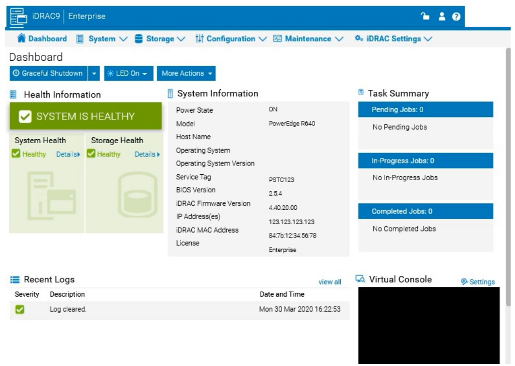
Access the System Logs:
In the iDRAC interface, navigate to the Dashboard tab.
Scroll down to the Recent Logs section or navigate to System Logs under Maintenance or iDRAC Settings (depending on the iDRAC version) to access detailed logs.
Filter Logs by Date:
Use the filter option to specify the date, focusing on entries from April 30, 2022. This will help narrow down relevant events.
Identify Power-Related Entries:
Look for log entries that mention power supply issues or voltage faults around the specified date. In this case, entries related to under-voltage faults or power supply failures will be critical.
Interpret the Log Entries:
Based on typical power fault logs, consider the possible answers:
A . Under voltage fault detection on power supply 1: Indicates a voltage issue was detected on PSU1.
B . Power supply 2 has failed: Indicates PSU2 has completely failed.
C . Under voltage fault detected on power supply 2: Indicates a voltage issue was detected on PSU2.
D . Power supply 1 has failed: Indicates PSU1 has completely failed.
The specific log entry depends on the exact wording in the logs. However, from the options provided, if the administrator received a notification about a power issue, the most likely scenario involves a failure or under-voltage detection.
Question 5
The customer implemented ten Dell PowerEdge R660 servers in their data center. The environment also has two MX7000 chassis. The system administrator requires a management application that can help holistically manage and monitor the storage, server, and network environment.
What would be the recommended solution?
Answer : B
Selecting a Management Application for Holistic Management of Dell PowerEdge Servers and MX7000 Chassis
Server Management and Configuration Tools (14%)
Explain the management interface options - LCC, racadm, OMSA, iSM, OME
System Administration (18%)
Configure BIOS, Storage, virtual media, networking, user access, lockdown mode, and group management
Understanding Customer Requirements
Environment:
Ten Dell PowerEdge R660 servers (rack servers).
Two MX7000 chassis (modular servers).
Requirement:
A management application that can holistically manage and monitor storage, servers, and network environment.
Evaluation of Options
Option A: iSM (Integrated Dell Remote Access Controller Service Module)
iSM is a software module that enhances iDRAC functionality by providing OS-level monitoring and management.
It is installed on individual servers to facilitate communication between the OS and iDRAC.
Limitation:
Not a centralized management application.
Does not provide holistic management across multiple servers and chassis.
Conclusion: Not suitable.
Option B: OME (OpenManage Enterprise)
Dell OpenManage Enterprise is a web-based, one-to-many systems management application.
Features:
Provides comprehensive management of Dell EMC servers, storage, and networking devices.
Supports both rack servers (R660) and modular chassis (MX7000).
Offers monitoring, configuration, deployment, and update capabilities.
User-friendly dashboard for holistic infrastructure management.
Conclusion: Correct Answer.
Option C: Group Manager
Group Manager is an iDRAC feature that allows basic grouping of servers for simplified management.
Limitations:
Limited to servers of the same generation and similar configurations.
Does not support the full range of management functions required.
Not suitable for managing storage and network environments.
Conclusion: Not sufficient.
Option D: OMSA (OpenManage Server Administrator)
OMSA is a software agent that provides a comprehensive, one-to-one systems management solution.
Installed on individual servers to manage and monitor hardware components.
Limitations:
Does not provide a centralized, holistic view.
Lacks the ability to manage multiple servers and chassis collectively.
Conclusion: Not appropriate.
Dell Operate Reference
Server Management and Configuration Tools (14%)
Explain the management interface options - LCC, racadm, OMSA, iSM, OME: Understanding the capabilities and limitations of various management tools is essential for selecting the appropriate solution.
System Administration (18%)
Group management: OpenManage Enterprise facilitates group management of diverse hardware.
Conclusion
OpenManage Enterprise (OME) is the recommended solution. It provides a unified management console capable of holistically managing and monitoring the customer's storage, server, and network environment, including both rack servers and modular chassis.
Question 6
Which configuration settings are installed when using Easy Restore?
Answer : A
Understanding Easy Restore Functionality
Server Troubleshooting (32%)
Explain Easy Restore, diagnostic utilities, and hardware diagnostic options
What is Easy Restore?
Easy Restore is a feature in Dell PowerEdge servers that simplifies the process of restoring system configuration settings after replacing the system board (motherboard).
Purpose:
Reduces downtime by automatically restoring critical configuration settings.
Eliminates the need to manually reconfigure settings after hardware replacement.
Configuration Settings Restored by Easy Restore
BIOS Settings:
Restores all BIOS configurations, including boot order, system settings, and performance options.
iDRAC Settings:
Restores Integrated Dell Remote Access Controller (iDRAC) configurations, such as network settings, user accounts, and management preferences.
NIC (Network Interface Card) Settings:
Restores network configurations for onboard NICs, including IP addresses, VLAN settings, and teaming configurations.
Explanation of Options
Option A: 'BIOS, iDRAC, and NIC'
Analysis:
Accurately reflects the settings restored by Easy Restore.
BIOS: System configuration and hardware settings.
iDRAC: Remote management settings.
NIC: Network configurations.
Conclusion: Correct Answer.
Option B: 'Virtual console, network, and SCP'
Analysis:
Virtual Console: Part of iDRAC features but not a configuration setting restored separately.
SCP (Server Configuration Profile): Used for exporting/importing configurations but not directly restored by Easy Restore.
Conclusion: Inaccurate.
Option C: 'iDRAC, BOSS, and partitions'
Analysis:
BOSS (Boot Optimized Storage Solution): A storage controller for boot drives; its settings are not restored by Easy Restore.
Partitions: Disk partitions are not restored by Easy Restore.
Conclusion: Incorrect.
Option D: 'Asset tag, passwords, and RAID'
Analysis:
Asset Tag: Restored by Easy Restore.
Passwords: May or may not be restored, depending on security policies.
RAID Configuration: Not restored by Easy Restore; requires separate backup and restoration procedures.
Conclusion: Partially correct but not the best answer.
Dell Operate Reference
Server Troubleshooting (32%)
Explain Easy Restore, diagnostic utilities, and hardware diagnostic options: Understanding what configurations Easy Restore handles is essential for efficient troubleshooting and system recovery.
Server Components (26%)
Define the different processor, memory options, and memory configurations: Knowing how system configurations are managed and restored.
Conclusion
Easy Restore reinstalls configuration settings for the BIOS, iDRAC, and NIC. This feature ensures that critical system configurations are preserved after replacing the system board, minimizing downtime and administrative effort.
Question 7
Under which heading can the user locate Lifecycle logs in the iDRAC Ul?
Answer : D
ocating Lifecycle Logs in the iDRAC UI
Server Troubleshooting (32%)
Explain the server logs and memory error
Understanding Lifecycle Logs
The Lifecycle Controller logs (Lifecycle Logs) are essential for tracking system events related to hardware configuration, firmware updates, and system health. These logs provide valuable information for troubleshooting and auditing purposes.
Accessing Lifecycle Logs in iDRAC UI
In the iDRAC web interface, administrators can navigate through various sections to access system information and logs.
To locate the Lifecycle Logs:
Log into the iDRAC Web Interface using your administrative credentials.
Navigate to the 'Maintenance' Tab:
This section is dedicated to maintenance tasks and logs.
Select 'System Event Log' or 'Lifecycle Log' under the Maintenance section to view the detailed logs.
Explanation of Options
Option A: System
Incorrect: This section provides system overview and hardware information but does not contain the Lifecycle Logs.
Option B: System Event Log
Incorrect: While this log contains events, the Lifecycle Logs are specifically found under the Maintenance section.
Option C: Diagnostics
Incorrect: This area is used for running diagnostic tests, not for accessing Lifecycle Logs.
Option D: Maintenance
Correct Answe r: The Lifecycle Logs are located under the Maintenance heading in the iDRAC
UI.
Dell Operate Reference
Server Troubleshooting (32%): Accessing and interpreting server logs is vital for diagnosing issues.
Explain the server logs and memory error: Understanding where logs are stored helps in efficient troubleshooting.
Server Management and Configuration Tools (14%): Navigating the iDRAC UI is crucial for system administration tasks.
Conclusion
By knowing that the Lifecycle Logs are located under the Maintenance section, administrators can quickly access important system event information necessary for troubleshooting and maintaining server health.